
INTRODUCTION
Surveying is the branch of civil engineering in which deals with measurement of relative positions of an object on earth's surface by measuring the horizontal distances, elevations, directions, and angles. Why do we need surveying in civil engineering? to prepare topographic map of land surface of the earth. highways, bridges, tunnels, dams etc are based upon surveying measurements. Thus, surveying is a basic requirement for all Civil Engineering projects.
Topics, we discuss here 👇
♀ Basics of surveying
♀ chain surveying
♀ compass surveying
♀ levelling
♀ plane table surveying
📝 CHAPTER-1 : BASICS OF SURVEYING
Direct/Indirect measurement (horizontal & vertical) of an object or relative points above and beneath the ground surface, is called surveying.
◆ Aim:- To prepare a map or plan.
◆Scale:- Two types of scale used in in surveying are-
● Metric scale - M.K.S (meter kg sec)
● British - F.P.S ( foot pound sec )
In india, we are use MKS scale for surveying and other measurements.
10mm = 1 Centimeter
10cm = 1 Decimeter
10Deci = 1 Meter
10m = 1 Decameter
10Deca = 1 Hectometer
10 Hecto = 1 Kilometer
1kg = 2.205 pound
1cm = 10 mm
1 inch = 2.54 cm
1 inch = 25.4 mm
1m = 3.28 foot = 39.36 inch
1 mile = 1.61 kilometer
1 Acare = 0.404 hectares
1 inch = 8 सूत (soot)
1 गज = 9 sq.foot
◆ Representation of scale in engineering-
● Engineering scale - 1cm = 50m
● Representative fraction (R.F) - most commonly use in surveying.
For example convert 1cm =50m In R.F scale, than first convert hole reading in cm,
So 1cm = 5000cm
Therefore R.F = 1/5000 or 1:5000
Example-1:- Find the R.F if scale is used in map 2cm=1m
Solution- 1m = 100cm,
R.F = 2/100 = 1/50 or 1:50
Example-2:- plot a distance as small map as 0.25mm and the scale of plotting is 1 in 10000. Find the actual distance crosponding to 0.25mm on map ?
Solution- focus on scale- 1 in 10000
We know that 1m =1000mm
10m = 10000mm
Therefore actual distance = 10×0.25 =2.5m
◆ Principle of surveying:-
● Two point of references:- in this method a point taking for measurement with reference for two known point. Method is drawn to line is triangulation.
● Work from whole to part- In this method a large area divided into various small triangle and measure each one and get the some of all.
◆ Primary Methods of Surveying:-
● Plane Surveying:- plane surveying is done for up to 260 square kilometer area only. The curvature of earth is neglected in this type of surveying.
● Geodetic Surveying- No limitation for measurements and curvature of earth is considered in this type of surveying.
◆ Classification of surveying:-
● Object Basis:- Engineering, Military, Mine and Geological Surveying
● Field Basis:- Land surveying- I)- Topographic, II)- Cadastral, III) City surveying,Hydrographic surveying & Astronomical surveying
● Instrument Basis:- Chain,Compass,Plane table, Theodolite, Techometric, photographical & Aerial surveying
● Method Basis:- Triangulation & Traversing
◆ lead and lift term used in earth work. Lead =30m and lift =5m
📝CHAPTER-2 : CHAIN SURVEYING
The principle of chain surveying is based on triangulation method.
◆ Aim:- To measure a actual distance of an object/point from station.
◆Components of chain surveying
♂ Chains
♂ Raniging rods
♂ Arrows
♂ Offset rod
♂ Cross staff
♂ Tapes
♂ Pegs
♂ Plumb bob
♂ Wooden mallet or hammer
1- Chains:- Five types of chain are using in chain surveying. Here I will discuss one by one.
I)- Revenue chain- L=33 foot ,Link = 16 , each link length = 2.0625 foot. Use in mile measurement
II)-Gunter's chain- L=66 foot, Link=100, each link length = 0.66 foot. Use in Cadastral survey
III)- Engineering chain- L= 100 foot, Link=100, each link = 1 foot.tallies use in each 10 foot.
IV)- Matric chain- L = 20m and 30m, If L=20m than link =100 and each link =20cm. If L=30m tha link=150 and each link=20cm. Tallies use in each 5m.
V)- Steel chain- L= 20m and 30m, width= 12mm to 16mm and thickness= 0.3 mm to 0.6 mm.
2-Ranging rods- Ranging road made by GI (galvanized iron) with zinc coating. Ranging rod circular in shape and 25 mm dia rod possess the length 2m to 3m. Rod is divided white and red colour in each part of 20cm.

● Minimum 3 rods required for measuring the length of a line.
● Minimum 4 rods used in indirect ranging.
● Bad ranging is the resources of positive cumulative error.
3- Arrows- Arrow is 4mm dia mild steel wire. The upper dia of Arrow is 50mm and the overall height is 400mm.

● Arrow use to measure the end to end length of a chain.
4- Offset rod- it is similar to ranging rod.But square type in the shape. Usually 2m,3m and 4m length of Offset rod used in surveying.
5- Cross- Staff- staff generally use to line of sight of a line during survey. Cross-staff are following to type-

● Metallic Cross-staff:- Metallic cross-staff with two object vane and two eye piece. Pivoted on 2.5cm dia and total height is equal to 1.2 to 1.5m.
● Franch staff- this is octagonal (4 object vane and 4 eye piece) consist width=10cm and height =15cm
👉 Open staff is more accurate as compared to octagonal and other staff.
6- Tapes- Total four types of tapes are used in survey.
● Cloth or linen tape- width=15mm and length = 10 to 15 m
● Metallic tape- identification of such tape is brass cap fixed at zero end. Total length of metallic tap is 15 to 20m
●Steel tape- width =6mm to 16mm, steel tape found in various length I.e 1m,2m,5m,10m,15m, 20m,30m,50m etc. Each 1m= 200 parts and each part is 5cm.
● Inver tape- Inver tape made of alloy of steel (64%) and nickel (36%). The thermal coefficient of Inver tap nearly zero, so widely used in surveying for more accuracy.
7- Pegs- pegs is used to mark the points or station. Pegs made by either wood or iron. Wooden pegs dimension is 2.5cm×2.5cm and length = 15 to 30cm. While iron pegs is used with 1cm dia.

8- Plumb bob- A conical weight suspended through a strong thread. Plumb bob is use to measuring the vertical level and centering of an object.
9- Wooden mallet- this a hammer,used to pull in pegs. The head circular dia =10cm and total length of head = 15 to 20cm. The length of handle = 45cm.

◆ Various correction in chain surveying-
● True length = measured length× (L'/L)
Here L'= incorrect length
● True area = measured area× (L'/L)^2
● True volume= measured volume× (L'/L)^3
● Pull correction Cp= (P-P.)L/AE
● Temperature correction Ct= α(Tm-T)L
● Sag correction Cs= Lw^2/24P^2
● slope correction = h^2/2L
● Vertical alignment = 2Lsin^2θ/2
📝CHAPTER-3: COMPASS SURVEYING
Compass surveying is based on traversing. Compass used only for horizontal angle measurements. Compass is less accurate as compare to theodolite. Compass box made by the brass. Error in compass found by local attraction. Compass is classified into to board categories-
I)- Prismatic Compass
II)- Surveyor Compass
1-Prismatic Compass- The prismatic compass is based on whole circle bearing. In this the bearing of compass is 0° at south and 180° at north in direction. The permissible error in prismatic compass surveying is 1 in 340. Least count of prismatic compass is 30' (30 minute)
2-Surveyor Compass- The surveyor compras is based on reduce or quadrant bearing. In this the bearing of compass is 0° at north or south and 90° at east or west. Least count of surveyor compass is 15' (15 minute)
◆Bearing of line- The horizontal angle made by a survey line with reference of some meridian or bearing, called Bearing of line. A survey line can show three types of bearing or meridians as given below-
I)- True meridian or True Bearing
II)- Magnetic meridian or Magnetic Bearing
III)- Arbitrary meridian or Assumed Bearing
● True Meridian- when a survey line passing through geological pole. N-S pole is called geological pole. True bearing called by a another name that is Azimuth Bearing.

● Magnetic Meridian- when a survey line deflect with some angle from geological poles due to local attraction, called Magnetic Bearing.

● Arbitrary or Assumed Meridian- when a line assumed from station to object without considering bearing called Arbitrary or Assumed bearing.
◆ Conversion of Bearing W.C.B to R.B and R.B to W.C.B-

This table showing conversion of WCB to RB but you can convert the same formula for WCB from same table.
For example. The bearing of line is N45°0'W, and ask to you find the whole circle bearing?
Solution:- Just se the poles of bearing line, and take the formula of R.B from above table.
Here R.B = 360° -W.C.B,
Now, W.C.B = 360° - R.B
Therefore W.C.B = 360° - 45° = 315°
◆ How to find the Back Bearing of a line ?
Back bearing = Fore Bearing ± 180
Note- This formula work only when fore bearing or back bearing given in W.C.B system. Not used in R.B, In the case of R.B just required to change the pole with opposite side pole.
R.B example- Fore bearing of a line is N30°45'E and required to find the back bearing.
Solution:- just need to change the pole with opposite poles.
Here N change with S, and E change with W
So Answer is S30°45'W
W.C.B example- Fore bearing of a line is 60° find the back bearing of line ?
Solution:- first see the value is grater than 180° or less ? If less, than formula use as -
B.B = F.B + 180°
If F.B grater than 180°, than formula use as-
B.B= F.B - 180°
Here the value is less than 180°, therefore
B.B = F.B + 180° = 60° + 180° = 240°
◆ Magnetic Dip- the slope of bearing needle in equator called Magnetic Dip. E-W pole is called equators. Magnetic dip 0° at equators and 90° at poles.
◆ Magnetic Declination- The deflection of bearing needle in East and West direction due to local attraction called Magnetic Declination. If declination in East called east declination and if declination is west called west declination.
● True Bearing = M.B ± Declination
● Magnetic bearing = T.B ∓ Declination
Mind pls👇
♂ In case of T.B, east declination is positive and west declination is negative.
♂ In case of M.B, east declination is negative and west declination is positive.
◆ Sum of the included Angle = (2n-4)90°
📝CHAPTER-5: PLANE TABLE SURVEYING
Plane table is the graphical method of surveying. Used where great accuracy is not required.
Components used in plane table surveying-
♀ Plane table with stand
♀ Alidade
♀ Trough Compass
♀ sprit level
♀ U- fork with plumb bob
♀ Drawing sheet
♀ water proof sheet
♀ chains / tape
♀ Ranging rods
♀ Pegs
♀ Scale card
♀ Hammer
1- Plane Table and stand- Plane table in various two size. 30cm×40cm as a small and 65cm×75cm as a large size table. Tripod stand use below the table about 1.25m height.
2- Alidade- Two types of Alidade used in plane table surveying. First is plain alidade, approx 50 cm to 60cm length. Second is telscopic Alidade. Telscopic Alidade is use to horizontal as well as vertical measurement. Alidade use in plane table for line of sight.
👉 The bevelled edge is also called fiducial edge.
3- Trough Compass- Trough compass is used to mark the north before plotting map.
4- sprit level- it is used for level the table across over a horizontal surface.
5- U-fork and plumb bob- U-fork is used to holding the plumb bob at the centre of station.
6- Drawing sheet - Various types of drawing sheets used in surveying are-
Ao = 841mm × 1189mm
A1 = 594mm × 841mm
A2 = 420mm × 594mm
A3 = 297mm × 420mm
A4 = 210mm × 297mm
◆ Standard dimensions of engineers drawing board-
Do = 1500mm × 1000mm × 25mm
D1 = 1000mm × 700mm × 25mm
D2 = 700mm × 500mm × 15mm
D3 = 500mm × 350mm × 10mm
👉 Other point is same as chain survey. so no need to discuss further here. Inver tape is used for plane table surve to eliminate the thermal error.
👉 Angle of alphabet/ letter writing -67.5° to 75°
◆ Methods of plane tabling- In the plane tabling, four various methods are used-
I)- Radiation
II)- Intersection
III)-Traversing
IV)- Resection
1- Radiation- Objects are plotted by drawing rays from the instrument station toward them.

Procedure-
● Select a ground station point P, all the object must be visible from this station.
● Set the plane table just above this station point and do centring or levelling. Mark the north on sheet and fixed a plot the point P on sheet.
● Take the alidade and do line of sight the object one by one from station and plot the rays on sheet by selection of a scale. like 1cm = 50m
● Finally meet all the point one to another and prepare the map or plan.
2- Intersection- Drawing of an objects like Inaccessible Objects, Broken Boundaries as in case of river etc. This method is suitable when object distance is large from a station.
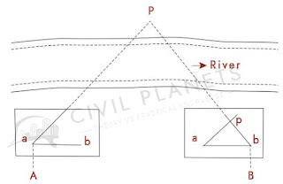
Procedure-
● Select two ground points A and B in such a way that all the object points to be located from them.
● set the table on station A and do centring and levelling. Mark the north and Intersect all the object from A and draw there rays on sheet with reference of scale.
● Now shift the table in station B and repeat the same process as same as A.
● Meet all the points on sheet and prepare a map or plan.
3- Traversing- A traverse consist of series of straight lines connected together. This method is similar to compass or theodolite traversing.
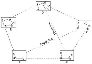
Procedure-
● Select all points in which a graph or map plotted. Like A,B,C,D &E
● Set the table A and do centring & levelling as before above all methods. Now bisect or line of sight nearest station or point from this station. Plot the rays on sheet with some reference of scale.
● Shift the table one to another station or point one by one and bisect each other and draw the ray as above mentioned.
● meet all the points on sheet and prepare a map or plan.
4- Resection- By means of sight taken toward known points which have been plotted.

Procedure-
● Select two known points A and B, Where the station P is visible.
● Set the table A and do centring & leveling. Now set a ranging rod at B as back sight and draw the ray as some reference of scale on sheet. set the alidade at A and draw a ray toward the Station P.
● shift the table at station P and bisect the point B and draw a ray withe same scale reference as previous.
● Meet a the points on sheet and prepare a plan or map.
◆ Problem in plane table-
I)- Two points problem
II)- Three points problem
1- Two points problem- Observing two well defined points which are visible from the instrument station and whose position have been already plotted on the plan previously. Method used in two point problem is Resection and Orientation.
2-Three points problem- Observation of three well defined points which are visible from the instrument station whose position have been previously plotted on the plan. Method used in two point problem is Resection and Orientation. Three points problem resolving by following three methods are-
● Bassel's graphical method
● Mechanical or Tracing Paper Method
● Trial and Error or Lehmann's method
Comments
Post a Comment